In my daily life, I often needed to use certain shortcut keys — and sometimes, those shortcuts actually caused me more trouble than they solved. That’s when the idea came to me: what if I could map these shortcuts onto a custom keyboard — or rather, a keypad — where each key would be assigned to a specific shortcut? Then, whenever I pressed that key, it would automatically trigger the shortcut for me.
After a while, I thought it would be great to add a couple of volume knobs as well. I made those using two potentiometers and connected them to the keypad so I could control the Windows volume or even zoom in and out directly from the same device.
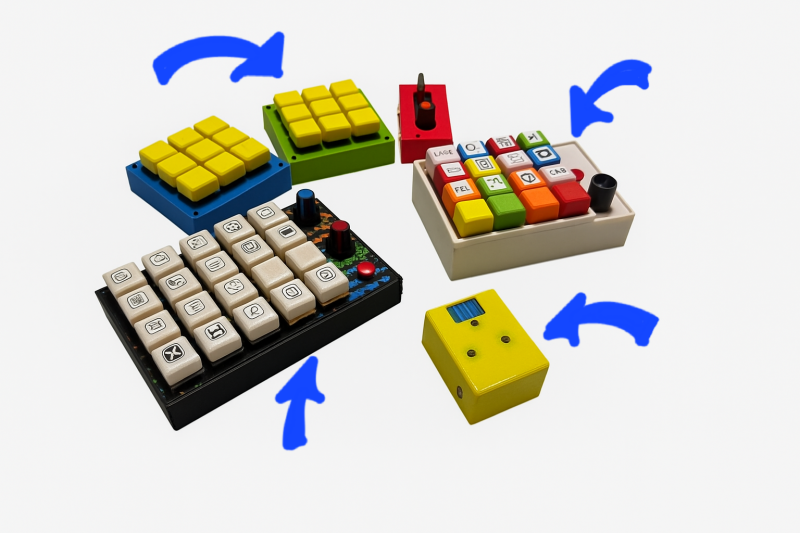
Later on, I realized I needed more shortcut keys, so I upgraded the keypad from 16 keys to 20. And eventually — as you can see in the photos — I figured out that it’s not always necessary to use all 20 keys or even the volume knobs all the time. So I designed the keypad in a modular way, meaning the parts can be attached or detached depending on my needs. I’ll explain how I built that in more detail using some pictures below.
NEEDED PARTS:
- Arduino pro micro (ATMEGA32U4 USB-C)
- Cupper wires
- Non-coated cupper wires
- Cherry Mx keys
- Micro tacktile push buttons
- USB-c cable
- Pc/laptop
- Soldering iron
- Some basic soldering skills
- 3d printer
- QMK MSYS (download for free from the official website)
- QMK Toolbox (download for free from the official website)
Steps:
- First we have to print the 3d files on a printer - i use anycubic kobra 3.
- Now we would have 3d mesh, box and key caps.
- Place the cherry mx keys inside the mesh.
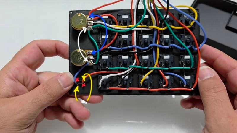
- As shown in the picture each key has two pins - marked with blue and red arrows.
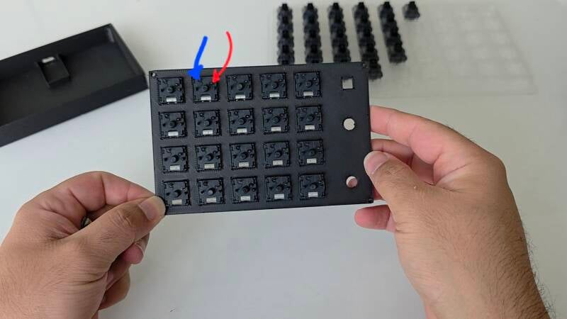
We have to use the matrix method for this keypad. With this method we need less pins on the arduino board and support more keys. To achieve it we have to connect all row pins in each row together and all column pins in each column together. In this case I made a 4x5 keypad so we would need 4 pins for rows and 5 pins for columns that will cover 20 keys in this project.
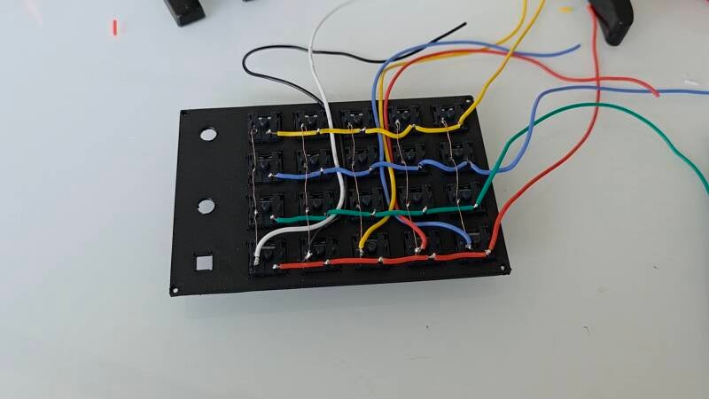
I used non coated cupper wires to connect columns and covered wires to join rows, in this way the rows and columns wires do not short the circuit. Then we move to connect the pins for potentiometer. Each potentiometer has 3 pins - as shown in the following picture. One of the side pins (up to your choice) have to be connected to Ground (GND) pin and the other one to the Positive (VCC) pin. The middle pin have to be connected to one of the A pins on the arduino board.
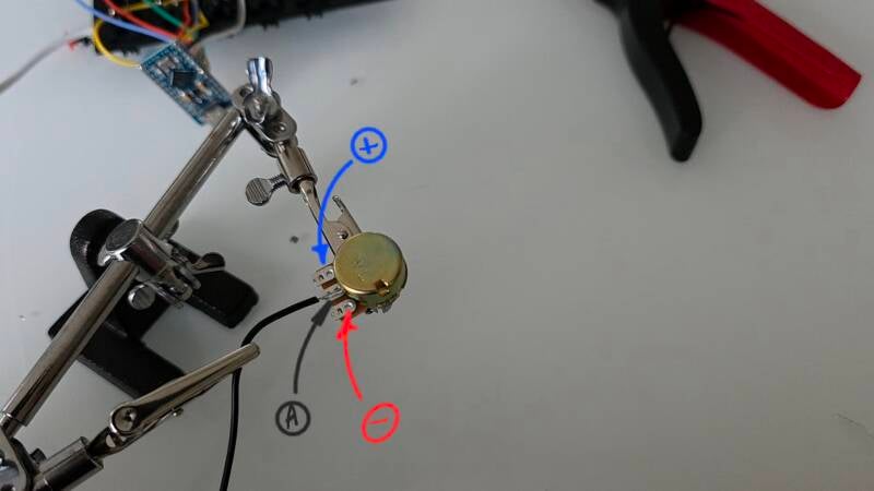
Now we are going to connect the two potentiometers together and place them on the mesh. We share VCC and GND pins with both potentiometers - unfortunately there is just one VCC pin in pro micro so we have to share it for both of the potentiometers in this way. As it is visible in the following picture we can connect them to each other. We have to use the tacktile micro push button as well to put the board on listening mode to be able to program it as it is pushed. For this purpose we have to use two pins of the micro button in X setup. One of the pins have to be soldered to GND pin on the arduino and the next one to the RST pin. We can use the GND pin on the potentiometer as shown in the image.
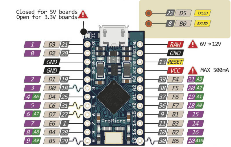
Now we have to connect each of the wires to corresponding pins on the arduino. as it i :s visible on the following image there are pins marked with 2 to 15 and A0 to A3 on the board. For Cherrzy MX keys we have to use the 2 to 15 pins as they are digital pins and for potentiometers we have to use the A0 to A3 pins as they could be recognized as analog pins by Arduino. Each pin has a different ID in QMK firmware.
- 2 : D1
- 3 : D0
- 4 : D4
- 5 : C6
- 6 : D7
- 7 : E6
- 8 : B4
- 9 : B5
- 10 : B6
- A0 : F7
- A1 : F6
- A2 : F5
- A3 : F4
Now download and install both QMK MSYS and QMK toolbox. After finishing installing these files follow the steps:
- open This PC
- open Drive C
- open users
- open your user folder
- open qmk_firmware folder
- now download the files from the link in this post
- extract the contents and copy them as:
- make a new folder in the root folder of qmk_firmware : Keyboards with your desired name
- open the folder and paste the keyboard.json here
- make a new folder here and name it keymaps
- open keymaps folder
- make a new folder here and name it default
- open default folder
- paste the rules.mk and keymap.c files here
- Now we are going to configure the keys functions:
- open the keymap.c file with note pad (better option is Visual C code studio software)
- there is a section in this file that you will find the shortcut key codes such as KC_LCTL...
- you can change them to your wish
- you can find each key code in qmk website
- after setting them go to the root folder of your keyboard and open keyboard.json
- here you can find the pins that you can set them up in the way that you connected rows and columns to the board
- After this step we need to compile the keyboard and upload it to the keypad:
- Open QMK MSYS
- type the following command: qmk compile -kb (keyboard name) -km default and hit enter
- it takes some time
- when it is finished a file with the file name as your keyboard name _default.hex in the qmk_firmware folder which is our compiled and ready to upload keyboard firmware file.
- open QMK Toolbox
- connect the keypad using USB C cable to computer
- hit the open button and choose the .hex file and click open
- turn the check box on beside autoflash option
- push the micro push button on the keyboard
- you will hear a sound like disconnecting and connecting a USB device and it automatically starts to flash it.
Download links for 3d files and keyboard files:
https://drive.google.com/drive/folders/1bWmkJbmEHbj2XcTbK0JVu0WhNTa9eTHz
Add comment
Comments